RC Charging Circuit: Time Constant Lab
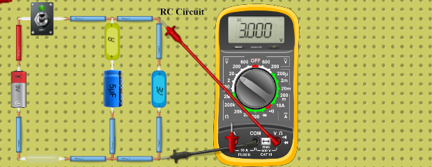
A 10 V battery charges a 1000 µF capacitor through 1 kΩ: τ = RC = 1 s. Read 63 % at 1 s on the NGSpice chart, then watch it discharge on the V meter.
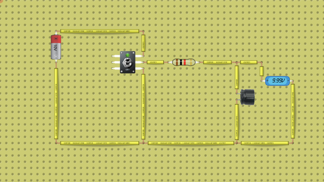
Use this circuit in class: RC circuit lab: charging, discharging and the time constant
Want to build your own circuit? Start a new circuit in the circuit simulator
Teaching with circuits?
Create a classroom, give your students a circuit to build, and review what they submit. Try it free with one classroom and up to 5 students.
Try the free classroom demoHow it works
A capacitor does not charge at once: through a resistor its voltage rises as Vc = Vs(1 − e−t/RC). With 1 kΩ and 1000 µF the time constant τ = RC is 1 second, so the capacitor reaches 63 % of the 10 V battery after 1 s and is practically full after 5 s.
The two-way switch connects the resistor to the battery (charging) or to its negative side (discharging). The V meter across the capacitor shows both; in the full lab the NGSpice Time Domain chart plots the charging curve so you can read τ off it.
What's inside
- 1× Battery
- 1× Resistor (1 kΩ)
- 1× Capacitor
- 1× Switch
- Measured with Voltmeter/Ammeter